

Select RF IP by the job it needs to do.
Amplify a weak signal, build an on-chip filter, drive an antenna, or convert RF energy to DC. Compare the circuit IP against your target band, process, impedance, and performance goals.
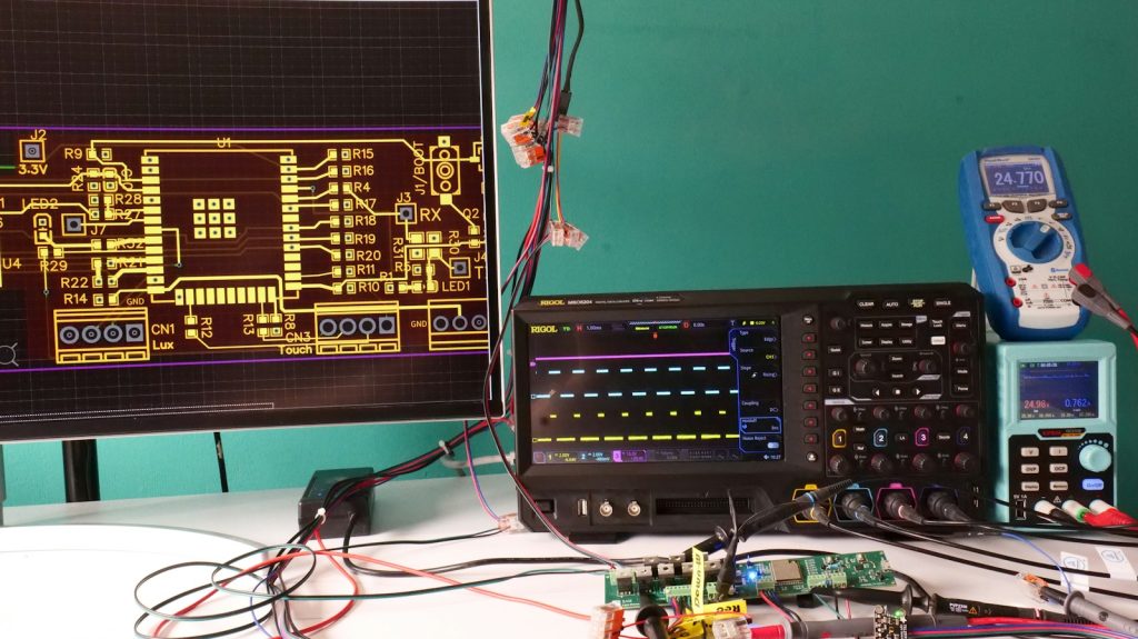
Electronics-lab context photograph by Axel Richter / Unsplash.
Explore the RF portfolio
CC-201IP & CC-202IP
For low-noise signal amplification, compare the two variants using gain, bandwidth, and noise specifications. Start with the datasheet, then discuss your input signal and process requirements.
CC-203IP Super Inductor
For LC filters and resonant circuits, explore customizable on-chip inductors in planar or stacked configurations. Compare inductance, quality factor at your operating frequency, and layout area.
CC-204IP
For antenna drive, explore Class AB power-amplifier IP with single or parallel stages. Define the required band, output power, antenna impedance, and noise performance before selecting a configuration.
CC-205IP
For RF-to-DC conversion, explore a CMOS rectifier with adjustable antenna matching. Compare input frequency and power, startup behavior, and output load using the datasheet curves.
Bring a specification. Leave with a next step.
Send your target frequency band, process, supply voltage, antenna or load impedance, and performance targets. Ask engineering about IP fit, customization, evaluation evidence, and licensing or quotation options.