

Build energy recovery into your circuit.
Choose CC-100 hardware for board-level evaluation or circuit IP for chip integration. Compare the connection point, process, and power-integrity objective before selecting a design approach.
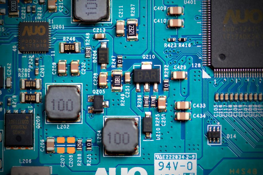
Circuit-board context photograph by Anne Nygård / Unsplash.
Choose the integration approach
CC-100
Start here for board-level integration. CC-100 circuitry uses switching-noise-activated feedback to recover a portion of bypass current. Ask about reference designs, supply requirements, and placement evaluation.
PowerPad
Choose PowerPad when the integration point is the power or ground bond pad. The IP uses feedback to reduce capacitor discharge and recharge demand, with minimal additional chip area as its design goal.
PowerGrid
Explore PowerGrid for integration across an IC power grid. Its approach combines capacitance multiplication, inductance control, EMI reduction, and switching-energy recovery.
CC-100IP-RF
For supply noise and RF sensitivity objectives, this IP can replace or work alongside on-chip decoupling capacitors. Evaluate emissions and circuit performance under the intended operating conditions.
CC-100IP-PI
Explore this variant when supply filtering and power integrity drive the design. Review impedance, capacitance behavior, and integration requirements against your power network.
From datasheet to design decision
The PowerPad datasheet reports up to 40% dynamic-power reduction under specified conditions. This is a circuit-level result, not a whole-server forecast. Share your process, pad or grid layout, supply range, and noise spectrum to define a relevant evaluation.